
Firstly, to avoid confusion, the Dennesen and the others like it are not suitable for setting up the Odyssey arms and SME arms which have unslotted headshells and are adjusted at the base. For this a two point protractor is needed. Also Arc protractors are not suitable as they are designed for arms with fixed mounting distance (pivot to stylus). However the Feickert has two null points and can be used without the gauge arm. So the following is just for information.
The principle of the original patented 1981 Dennesen alignment protractor and its later derivatives is primarily based on a concept that goes back to Percy Wilson in 1924 and before him to Bela Harsanyi in 1907.
Both were attempting to find a method to minimise tracking error in pivoted
arms, and came up with a way of doing so by using overhang and offset.
The overhang allowed the arc of the stylus to be such that it minimised
the variation in error, and the offset allowed the error itself to be
minimised for that overhang.
Once the limits of the arc
are chosen, there is a constant which follows from this. This constant
(which is also related to the radii of the two null points) was named by
Wilson as the Linear Offset
For
any pivoted arm, the inner and outer recorded radii of a record
determine the extent to which the tracking angle varies. As overhang is
increased, tracking angle also increases from inner to outer radii.
until there is a "best fit" arc which crosses a disc of given recorded
radii such that, with overhang and with increasing cartridge offset to
compensate for the tracking angle, the arm can cross the record with
reducing tracking errors. By angling the cartridge, the errors are
minimised, and at two points on the arc the error is zero. These
are the nulls. These points on the arc can be refined so that it is
distortion rather than tracking angle error that is minimised. This
gives rise to the various alignments - Lofgren A (Baerwald), Lofgren B,
Stevenson, and others, which minimise distortion in different areas of
the record depending on the desired outcome. Each of these alignments
has its version for particular recording standards - IEC, DIN, etc, or
can be modified to any recorded radii.
The Dennesen
U.S.patent number 4,295,277 cites Baerwald (who follows Lofgren) and
uses nulls of 2.6" and 4.76" which are nulls resulting from the
equations for IEC inner and outer recorded radii, of 2.375" and 5.75"
For the Dennesen, like the Acoustical Systems Uni-protractor, now called the Smartractor, and the Dr Feickert Analogue Protractor(both of which
use the Dennesen principle but don't particularly credit him), the
arm mounting distance (pivot to spindle distance, P2S) can be obtained
from two dimensions:
The distance to the arm pivot along the axis of the protractor's offset arm (alloy in Dennesen, acrylic in Smartractor) from the point where the null radius crosses it, is determined by sliding it to coincide with the arm pivot point.
Call this X.
Second:
The distance from the centre of the spindle extended along the null radius to the centre line of the alloy or acrylic protractor arm.
This distance varies depending on the alignment, and must adjust for each. However, you don't have to measure it if the device is set for a particular alignment (such as LofgrenA/Baerwald IEC in the Dennesen), as it is fixed and given by:
Outer Null minus Inner Null, then divide by 2,
Call this Y.
(For LofgrenA.Baerwald IEC this is 27.45. If the device is set for another alignment, then the same calculation applies with the appropriate nulls.)
This gives a right angled triangle, where the mounting distance (P2S) is given by:
the square root of: X squared plus Y squared.
So, if this distance has been set on the protractor by sliding the arm until the pointer is over the arm pivot, then the nulls must be in the correct position for the appropriate effective length relative to the pivot point, wherever it is. See the photo below from the web site of Origin Live:
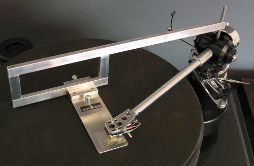
All that remains is to slide and/or twist the cartridge in its slotted headshell to align with the grid.
This applies to the Dennesen but only for the LofgrenA/Baerwald IEC alignment for which it is set up, unless modified. The Smartractor and Feickert have the facility to set up for other alignments.
This aspect (and the Acoustical Systems UNI-DIN alignment, which is, in effect, just the result of the Lofgren equations for different recorded diameters) is covered in more detail with an illustration of the basic geometry rectangle in another post here, concerning arm design geometry.
The accuracy of the method depends on how well you can position the protractor arm over your estimate of where the tonearm pivot is, and then, as with any protractor, how accurately you set up the stylus/cantilever/cartridge to the grid lines. Consideration of the degree to which small differences affect alignment can be found here, in a post about variations in spaindle size and small errors in alignment
The whole point of the Dennesen principle and its big innovation was to allow correct alignment with an existing (and, more importantly) an unknown mounting distance. If the distance has been set wrongly for a particular arm which requires a particular mounting distance, this would be corrected (if using a slotted headshell) by adjusting the effective length and cartridge offset (assuming enough adjustment) to match the null on the protractor.
Which begs the question, though, of why anyone using a protractor of this type would ever need to know the actual mounting distance. A device for measuring this is unnecessary if using the Dennesen, Smartractor/Uni-protractor or Feickert.
The principle of the Dennesen and the Smartractor/ Feickert could be refined to allow even simpler, more universal, and more accurate setup, particularly for SME arms which are adjusted at the base.